Here is an application from the FreeCAD FEM workshop: an I-beam supported at both ends is subject to its weight as well as a center load of 1000 kg.
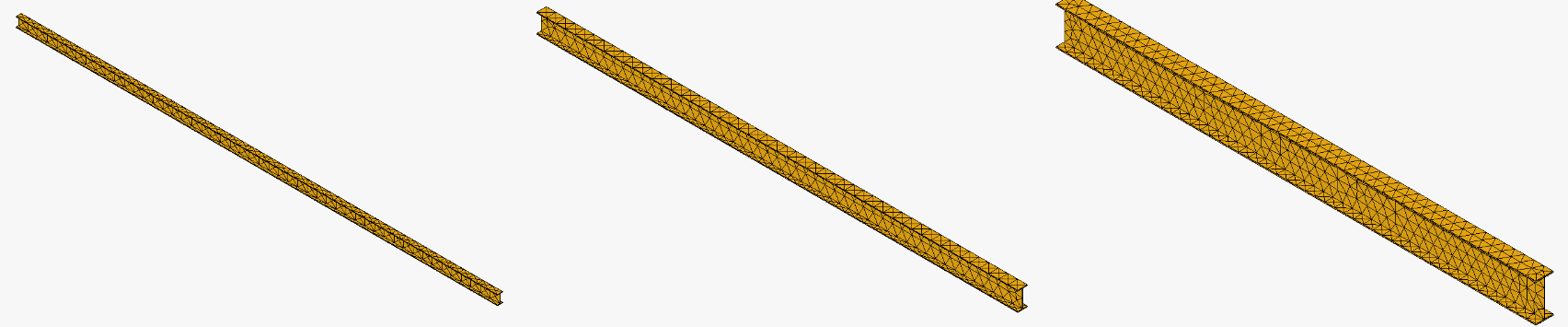
The beams considered here all have a length L of 5 m but various profiles: IPE100, IPE200 or IPE400 (this European nomenclature contains the height H of the beam, in mm; three other geometric parameters are necessary to define an IPE profile).
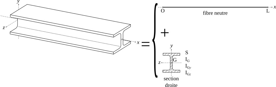
The classical analytical model of pure flexion, based on a sufficiently large length L in front of the height H, is described in this Wikipedia article, from which the following figure is extracted:
You can also download here a summary of the formulas used in this report as well as their encoding into a Calc spreadsheet (containing also the results discussed below).
The FEM workshop of FreeCAD can implement various mesh generators and finite element models. The combination used here is Gmsh for meshing and CalculiX for structural analysis (in static/linear mode).
Before comparing the two models (beam theory vs. FreeCAD/Gsmh/CalculiX), here are the Gsmh meshes used for the three beams considered (identical angle of view and zoom level):
Working with FreeCAD consisted in modeling an IPE profile (PartDesign and Sketcher workshops) then facilitating its modification thanks to the Spreadsheet workshop (relying on the parametric modeling feature of FreeCAD). On the other hand, for this exercise we did not automate the calculations with Python, nor did we take the time to visualize the results with ParaView (as many possibilities offered by FreeCAD).
Let’s first consider the deformation of the IPE100 beam, here exaggerated 10 times:
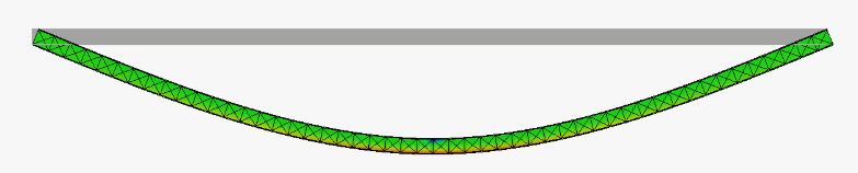
The deflection exceeds 7.6 cm and the stress $\sigma_{xxMax}$ (see form) reaches 380 MPa (in red), which is greater than the elastic limit $235 \text{ MPa} \leq R_e \le 355 \text{ MPa}$ of a general purpose steel (S235 to S355): a 5 m IPE100 beam cannot therefore withstand the mass of 1000 kg. On the other hand, the IPE200 and IPE400 profiles hold up according to this criterion: see the color code in the Calc spreadsheet.
The following table shows that the analytical and numerical models are in very good agreement, even in the case of IPE 100: indeed, these two models provide a linear elastic solution1, even if it is not appropriate.
| deflection | $\sigma_{xxMax}$ (MPa) | |||||
| IPE | analytic (mm) | numerical (mm) | difference (%) | analytic (Mpa) | numerical (MPa) | difference (%) |
| 100 | 76.3 | 76,7 | -0.5 | 383 | 384 | -0.2 |
| 200 | 7.03 | 7.21 | -2.5 | 70.0 | 69.9 | 0.2 |
| 400 | 0.667 | 0.764 | -12.7 | 13.0 | 13.0 | 0.0 |
The main difference comes from the H/L<<1 hypothesis of the analytical model, and it can be seen that the agreement becomes less good when the section increases. On the other hand, the agreement on $\sigma_{xxMax}$ is remarkable (and depends little on H/L !).
In conclusion, this exercise allowed us to test the proper functioning of the modeling tools offered by FreeCAD, in a configuration that we can validate with the analytical model. But obviously the numerical solution, although linear (elastic domain), is not restricted to H/L<<1 cases.
- Choosing a deformation analysis in FreeCAD/CalculiX didn’t change the results significantly... and we haven’t looked any further in that direction.↑